Underground Gold Mine Solution | Cut and Fill Mining Method for High-Grade Thin Vein Gold Deposits
1. What is Cut and Fill Mining?
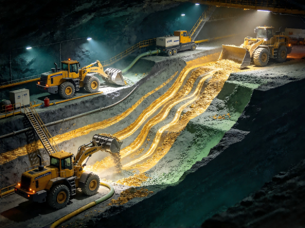
Cut and Fill Mining is an underground hard-rock mining method designed for narrow, high-grade gold veins where ore loss and surface subsidence must be minimized. The orebody is extracted in horizontal or inclined horizontal slices (cuts) from the bottom of the stope upward. After each cut is mined out, the void is immediately backfilled with cemented rock fill, paste fill or uncemented waste rock. The filled layer becomes the working platform for the next upper cut, providing ground support and preventing wall rock collapse.
This method is widely adopted for high-value, narrow gold veins in Peru (Ayacucho, Arequipa, Cajamarca), Central Asia and West Africa. It achieves the lowest ore loss and dilution among all underground mining methods, making it the preferred choice for high-grade underground gold deposits where every gram of gold matters.
1.1 Typical Cut and Fill Cycle Sequence
- Development — Drive access drift, undercut drift and raise access to the ore block.
- Drilling — Drill horizontal ring holes or breasting holes from the undercut level.
- Blasting — Blast the ore slice in a controlled manner to minimize wall damage.
- Mucking — Load broken ore with LHD (Load-Haul-Dump) machines and truck to ore pass.
- Scaling & Bolting — Scale loose wall rock, install rock bolts and mesh for safety.
- Backfilling — Deliver cemented rock fill / paste fill to the stope and compact to the desired strength.
- Repeat — Move up to the next upper slice and repeat the cycle.
2. Suitable Orebody Conditions for Cut and Fill Mining
Ideal Orebody:
- High-grade narrow gold veins (0.5 – 5 m vein width), steep dip (45° – 90°)
- Variable ore grade and geology — flexible stoping adapts to orebody geometry
- Weak or unstable wall rock — backfill provides immediate support
- Depth below surface where open-pit mining is uneconomic
- Environmentally sensitive areas — minimal surface subsidence, no large waste dumps
- Projects in Peru MEM-regulated areas where surface disturbance must be minimized
Not Ideal:
- Very thick massive orebodies (Longhole Open Stoping is more productive)
- Flat-dipping tabular deposits (Room and Pillar may be more suitable)
- Low-grade orebodies where backfill cost cannot be justified
3. Core Advantages of Cut and Fill Mining
- Lowest Ore Loss & Dilution — Recover 95%+ of ore, minimal waste rock mixing, critical for high-grade gold veins.
- Excellent Ground Control — Backfill supports walls immediately, safe operation in weak rock conditions.
- No Surface Subsidence — Filled stopes do not collapse, ideal for populated or environmentally sensitive surface.
- Flexible Geometry — Adapts to irregular vein shapes, pinches, swells and grade changes without major redesign.
- Waste Rock Utilization — Underground waste rock and tailings are recycled as backfill, reducing surface tailings and waste dump volume.
- Selective Mining — Can mine high-grade zones separately from low-grade zones, maximizing economic value.
4. Complete Equipment List for Cut and Fill Underground Gold Mine
4.1 Development & Production Drilling
- Development Jumbo Drill (2-boom / 1-boom drill jumbo for drift driving)
- Production Drill (long-hole drill / drill rig for ring drilling in stopes)
- Bolting Jumbo (rock bolting machine for ground support installation)
- Jackleg / Stopper Drill (handheld drill for small stope operations)
4.2 Mucking & Haulage (Underground Transportation)
- LHD Load-Haul-Dump Loader (underground diesel / electric LHD, 2 – 6 m³ bucket)
- Underground Mine Truck (articulated dump truck, 10 – 40 t payload, low-profile cab)
- Ore Pass (vertical ore chute with finger gate)
- Load Haul Dump Chute / Orepass Loading Pocket
4.3 Hoisting & Surface Transport (if Shaft Decline)
- Shaft Hoist (for deep shaft mines: friction hoist / drum hoist)
- Skip & Cage System
- Underground Decline Truck (if using decline instead of shaft)
- Belt Conveyor from shaft bin to surface crushing plant
4.4 Backfill System (Key Differentiator for Cut and Fill)
- Cemented Rock Fill (CRF) System — rock crushing & screening plant, cement mixing plant
- Paste Fill Plant (tailings dewatering to paste consistency, mixed with cement)
- Backfill Transportation System — borehole / pipeline / pneumatic delivery to stope
- Backfill Binder Silo (cement / fly ash silo)
- Water & Cement Mixing Station
4.5 Ground Support & Safety
- Rock Bolting System (rebar bolts, split set, cable bolts)
- Wire Mesh / Shotcrete Sprayer
- Scaler (scaling jumbo for loose rock removal)
4.6 Ventilation & Drainage
- Main Underground Fan (axial fan on surface + booster fans underground)
- Ventilation Ducting / Raises
- Sump Pump & Underground Water Tank
- Drainage Pump & Pipeline
4.7 Surface Processing Plant (After Ore Hoisted to Surface)
- Jaw Crusher / Cone Crusher (primary & secondary)
- Ball Mill (grinding to P80 150 – 200 µm)
- CIL / Flotation Circuit (depending on ore type)
- Elution & Electrowinning (if CIL route)
- Gold Smelting Furnace (doré production)
5. Typical Technical Parameters for Cut and Fill Stoping
|
Parameter |
Typical Range |
Note |
|---|---|---|
|
Orebody Width |
0.5 – 5 m |
Narrow vein |
|
Orebody Dip |
45° – 90° |
Steep vein |
|
Stope Height (per cut) |
2.5 – 4 m |
Horizontal slice height |
|
Stope Length |
40 – 100 m |
Along strike |
|
Ore Loss Rate |
3% – 8% |
Lowest among all UG methods |
|
Dilution Rate |
5% – 15% |
Minimal waste rock mixing |
|
Daily Production (single stope) |
50 – 200 tpd |
Multiple stopes can operate in parallel |
|
Backfill Strength (CRF) |
0.5 – 2 MPa |
Cemented rock fill unconfined compressive strength |
|
Cement Content (paste fill) |
3% – 8% by weight |
Depends on required strength |
6. Consumables & Spare Parts
6.1 Drilling & Blasting Consumables
- Rock Drill Bits (button bits, cross bits)
- Drill Rods / Drifters
- Blasting Explosives (emulsion / ANFO / dynamite, depending on regulation)
- Detonators & Fuses
6.2 Ground Support Consumables
- Rock Bolts (rebar bolts, cable bolts, split sets)
- Wire Mesh & Shotcrete (if required)
- Resin Cartridges (for rebar bolt installation)
6.3 Backfill System Consumables
- Cement (ordinary Portland cement)
- Fly Ash / Slag (partial cement replacement, cost reduction)
- Aggregate / Crushed Rock (for cemented rock fill)
- Tailings (dewatered paste, from processing plant)
- Water (mixing water)
6.4 LHD & Truck Wear Parts
- LHD Bucket Teeth & Cutting Edges
- Truck Tires & Brake Pads
- Hydraulic Hoses & Filters
- Engine & Transmission Spare Parts
6.5 Other Consumables
- Belt Conveyor Belts & Idlers
- Pipeline Wear Parts (backfill pipeline elbows, tee pieces)
- Ventilation Fan Filters & Belts
- De-watering Pump Seals & Impellers
7. End-to-End Project Flow
Orebody Development → Access Drifting → Undercut Drift → Ring Drilling → Blasting → LHD Mucking → Ore to Orepass → Hoisting / Truck to Surface → Primary Crushing → Grinding → CIL / Flotation → Electrowinning / Smelting → Doré Gold Bar | Underground Waste Rock / Tailings → Backfill Plant → Backfill to Stope → Next Cut Cycle
8. FAQ for Cut and Fill Underground Gold Mine Solution
Q1: Why is Cut and Fill Mining the recommended method for new gold projects in Peru?
A1: Most new gold deposits in Peru are narrow, high-grade quartz veins with variable wall rock conditions. Cut and fill achieves the lowest ore loss (3%–8%) and dilution (5%–15%), and produces almost no surface subsidence — which complies well with Peru MEM environmental and safety regulations. It is the default choice for new high-grade underground gold projects in Ayacucho, Arequipa and Cajamarca.
Q2: What is the difference between Cut and Fill and Shrinkage Stoping?
A2: Shrinkage stoping leaves broken ore in the stope as temporary support and requires no backfill. Cut and fill removes all ore immediately after blasting and replaces it with engineered backfill. Cut and fill is safer, has lower ore loss, and is now the preferred method under Peru’s stricter underground mining safety rules. Shrinkage stoping is mostly limited to older operating mines.
Q3: What backfill types are used in Cut and Fill Mining?
A3: Three common types: (1) Cemented Rock Fill (CRF) — crushed waste rock mixed with cement; (2) Paste Fill — dewatered tailings mixed with cement, pumped through pipelines; (3) Uncemented Rock Fill — waste rock only, for upper or non-critical stopes. The choice depends on stope depth, wall rock conditions and cost.
Q4: What production capacity can a typical Cut and Fill mine achieve?
A4: A single stope typically produces 50–200 tpd. A well-developed mine with 3–5 stopes operating in parallel can reach 300–800 tpd total. For larger orebodies, multiple mining blocks can be developed to increase throughput.
Q5: Do you supply the complete solution from underground development to gold production?
A5: Yes. We provide an integrated package: development drilling rigs, LHD and underground trucks, ore pass and hoisting system, backfill plant design, surface crushing-grinding-CIL/flotation plant, and long-term spare parts supply. We also provide on-site commissioning and operator training for high-altitude Peruvian mines.
Q6: Can the system handle high-altitude Peruvian mine conditions (3,500 – 4,200 m)?
A6: Yes. All diesel LHDs, trucks and generators are configured with high-altitude tuning, cold-weather insulation and derated power output. Backfill pipelines, water systems and electrical equipment are also designed for low-pressure, low-temperature conditions common in the Andes.
Q7: What information do you need to prepare a Cut and Fill mining proposal?
A7: We need: orebody geological report (width, dip, depth), wall rock quality (rock classification), ore grade (Au g/t), target production rate, access method (shaft / decline / adit), and mine site location. Our mining engineers will then prepare a stoping design, equipment list and backfill system layout.
Ready to Build Your Cut and Fill Underground Gold Mine?
Send us your orebody geological report, vein geometry, wall rock condition and target production rate. Our mining engineers will prepare a customized Cut and Fill stoping design, equipment list and backfill system layout for your project.
What to send: Orebody geometry / Au grade / wall rock classification / target tpd / access method (shaft / decline) / mine location & altitude